Recommended Products
Latest Posts ⚡
Building a High-Speed AI Cluster with 4 DGX Spark Systems
For large AI models, the limiting factor is often not just compute performance, but memory capacity. When a model no longer fits within the memory of a single system, the workload must be distributed across multiple nodes. However, multi-node deployments are not used solely to accommodate models that are too large for one system. Even when a model can run on a single DGX Spark, using two or four systems with the right parallelism strategy and runtime configuration can increase aggregate token throughput and concurrent request-processing capacity.
There is an important distinction here: adding more nodes does not automatically improve performance in every scenario. The model architecture, inference engine, parallelism strategy, request pattern, and inter-node communication overhead all have a direct impact on the outcome. The real benefit of a multi-node system therefore comes not from the hardware count alone, but from optimizing the compute and communication layers together.
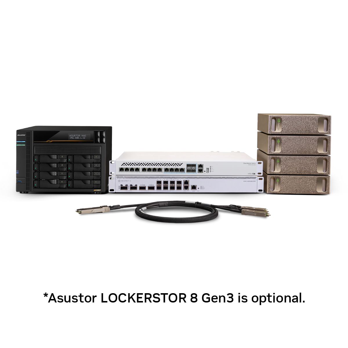
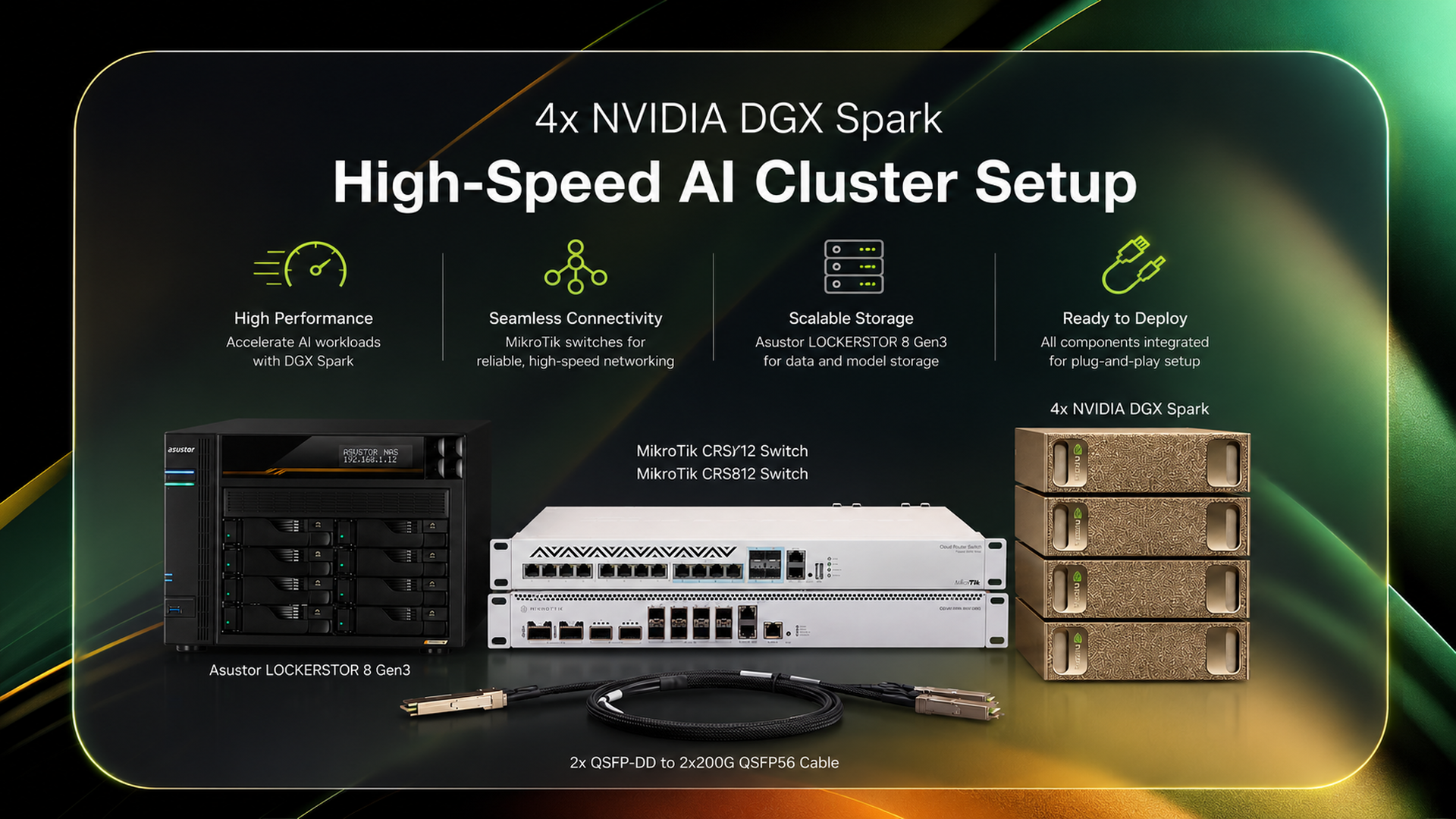
In this project, four NVIDIA DGX Spark systems were connected over a high-speed network and configured as a single AI cluster. The goal was to run models that could not be hosted on one Spark alone, while also increasing token throughput for suitable workloads.
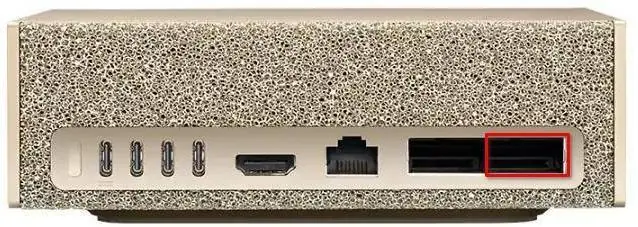
The 10GbE RJ45 management network was separated from the 200GbE compute network provided by the ConnectX-7 interfaces. When both ConnectX-7 interfaces on the compute fabric were used together, approximately 200 Gbps of aggregate RDMA bandwidth was achieved between the Spark systems, with latency measured at 1–3 microseconds. The infrastructure was then validated under a real workload by running GLM-5.2 across all four nodes.
Why Build a Cluster?
When a model does not fit within the memory of a single GPU or system, several parallelism strategies can be used.
Tensor parallelism splits large tensors and computations within an individual model layer across multiple GPUs. Each GPU processes part of the same layer, and the intermediate results are exchanged between devices. This approach is particularly useful when a single layer or the model weights cannot fit into the memory of one GPU.
Pipeline parallelism divides the model into groups of layers or sequential stages. The first layers run on one GPU or node, while later layers run on another. Data, typically organized into micro-batches, moves through these stages like items along a production pipeline. Pipeline parallelism is especially useful in multi-node deployments because different parts of the model can be placed on separate devices.
Tensor and pipeline parallelism can also be combined. The most appropriate strategy depends on the model architecture, memory requirements, and the capabilities of the inference stack.
Because GPUs continuously exchange data during distributed execution, compute performance alone is not enough. If the network is slow, GPUs spend time waiting for data from other nodes instead of performing calculations. Cluster performance must therefore be evaluated as a combination of GPU compute capability and inter-node communication performance.
Architecture
The cluster was built on two physically separate networks:
- Management network (10GbE): SSH access, system administration, software updates, and NAS traffic
- Compute network (200GbE): RDMA and distributed model communication
This separation prevents intensive compute traffic from interfering with routine management and storage operations. The main components and their roles are summarized below:
| Component | Role |
|---|---|
| 4× NVIDIA DGX Spark | Compute nodes running the distributed model workload |
| MikroTik CRS312 | 10GbE management network and NAS connectivity |
| MikroTik CRS812 | 200GbE compute network |
| ASUSTOR AS6808T | Shared storage for models and datasets |
| sparkrun | Cluster setup and multi-node workload management |
The 400G QSFP-DD ports on the CRS812 were split into two independent 200G QSFP56 links using passive breakout cables. This allowed a single physical switch port to provide separate 200G connections to two Spark systems.

Why RDMA and RoCEv2?
With conventional TCP/IP communication, data passes through the operating system networking stack. This process can introduce CPU overhead, memory copies, and additional latency. In large-model workloads, where high volumes of data are continuously exchanged between nodes, that overhead becomes more significant.
RDMA, or Remote Direct Memory Access, enables data to be transferred from the memory of one system to another while reducing the load on the CPU and operating system networking stack. This can deliver lower latency and higher effective bandwidth.
This cluster uses RoCEv2, or RDMA over Converged Ethernet version 2, to carry RDMA traffic over an Ethernet fabric. Ethernet is inherently a lossy network, however, so packet loss and congestion behavior must be carefully managed for RoCEv2 to operate efficiently.
The following settings were therefore applied to the compute network:
- MTU 9000: Reduces packet-processing overhead by carrying large transfers in fewer frames
- DSCP 26 → TC3: Places RoCE traffic into a dedicated traffic class
- PFC: Temporarily pauses the affected traffic class during congestion instead of dropping packets
- ECN and CNP: Detect congestion early and signal the sender to reduce its transmission rate
PFC was enabled only for TC3, the traffic class carrying RDMA traffic. SSH and ordinary TCP traffic were not placed in the lossless queue.
Why the MikroTik CRS812?
NVIDIA Spectrum switches are a well-established option for high-speed AI fabrics. This project, however, targeted a compact and cost-conscious four-node lab cluster.
The CRS812 provides the features required for this design, including 400G QSFP-DD ports, breakout support, hardware-offloaded QoS, PFC, ECN, and DCBX. With the correct configuration, approximately 100–111 Gbps of RDMA throughput per link was achieved.
This does not mean that the CRS812 can replace a data-center-class switch in every deployment. For this four-node DGX Spark cluster, however, it provides a practical balance between cost and performance.
Preparing the Nodes
Before cluster setup, all four Spark systems were brought to the same operating system and firmware level. This step is more important than it may appear. Outdated firmware on high-speed network adapters can prevent the expected performance from being reached even when the network configuration is otherwise correct.
The operating system packages and firmware were updated, and the DGX Dashboard was checked for any remaining updates. On the Docker side, all nodes were configured to use the same storage backend, and overlayfs through the containerd snapshotter was verified.
For the management network, the 10GbE port on each Spark was connected to the CRS312 and assigned a static IP address. SSH access, system updates, sparkrun management, and NAS connectivity were all provided through this network.
What Does sparkrun Simplify?
Although four systems can be managed individually, repeatedly running the same commands on every node, configuring SSH keys, and manually launching distributed workloads quickly becomes error-prone.
sparkrun is a toolkit that creates an SSH mesh between DGX Spark nodes and simplifies multi-node model execution. In this deployment, sparkrun was used to:
- Configure passwordless SSH access between nodes
- Prepare the ConnectX-7 networks
- Configure user and Docker permissions
- Launch the model from a single recipe file
Although sparkrun automates many of the setup steps, the host-side DCB configuration was applied separately. DSCP 26 traffic was mapped to priority 3 on the ConnectX-7 interfaces, and PFC was enabled for that priority. A systemd service was created to persist these settings across reboots.
Validating the Network
The network was validated layer by layer before any model workload was launched.
Connectivity between the compute IP addresses was tested first. The ping -M do -s 8972 command was then used to confirm that MTU 9000 worked end to end.
At the TCP layer, iperf3 measured approximately 100–120 Gbps of throughput. The RDMA tests produced the following results on each ConnectX-7 subnet:
- 100–111 Gbps write bandwidth
- 95–110 Gbps read bandwidth
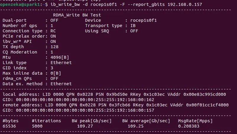
Across both subnets, the Spark systems achieved approximately 200 Gbps of aggregate RDMA bandwidth. The ib_write_lat test measured latency at approximately 1–3 microseconds.
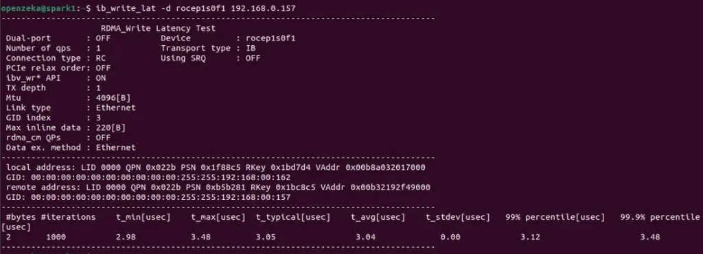
These figures matter beyond network benchmarking. When tensor or pipeline parallelism is used, the time required to transfer data between nodes directly affects overall model performance.
Running a Real Workload with GLM-5.2
After the network tests were completed, GLM-5.2 was deployed across four Spark systems using a tensor parallel size of 4.
The model was launched through sparkrun using a single recipe:
sparkrun run glm52-qt-dcp4-4spark.yaml
In addition to the model definition, the recipe specifies the container image, memory limits, KV cache settings, quantization format, and vLLM runtime parameters. This makes the deployment reproducible without requiring the full command line to be reconstructed each time.
The Application startup complete. message confirmed that all four nodes were participating in the same distributed model deployment.
In a benchmark performed after the service was ready, the GLM-5.2-Int4 model achieved 20.16 output tokens per second at concurrency 1. This result confirmed that the distributed system could serve a real end-to-end inference request, rather than merely loading the model successfully.
Shared Storage
The ASUSTOR NAS was used as shared storage so that model files did not need to be copied separately to every node. Its two 10GbE ports were connected to the CRS312 using LACP, and the NFS share was mounted on all Spark nodes.
LACP does not automatically increase a single file transfer to 20 Gbps. Its benefit comes from distributing multiple connections and traffic flows across the two physical links.
Model weights, datasets, and benchmark outputs were stored in the shared NAS location.
Conclusion
This project transformed four independent DGX Spark systems into an integrated AI cluster running on shared networking and storage infrastructure. Separating management and compute traffic, implementing RoCEv2/RDMA end to end, centralizing node management with sparkrun, and using a shared NFS volume resulted in an infrastructure that is both manageable and stable.
The resulting platform can run models that exceed the memory capacity of a single Spark. Even when a model already fits on one system, multiple Spark nodes can be used with the right parallelism and serving configuration to increase aggregate token throughput and support more concurrent requests.
The approximately 200 Gbps of aggregate RDMA bandwidth, 1–3 microsecond latency, and successful four-node GLM-5.2 deployment demonstrate that the architecture works not only in theory, but under a real large-model inference workload. With the networking, storage, and cluster-management layers designed as a single system, DGX Spark can serve as the foundation for a compact yet capable distributed AI platform.
All commands, MikroTik switch settings, DCB configuration, network tests, NAS setup, and troubleshooting steps are available in the detailed DGX Spark 4-Node AI Cluster Deployment Guide.
To deploy a similar DGX Spark cluster, the complete system can be ordered from openzeka.com. Cluster networking, node configuration, and basic commissioning are included at no additional cost with the system purchase.